
Custom motherboard for my first robot
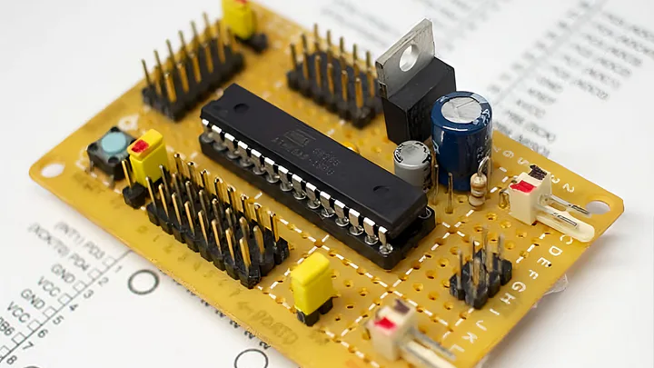
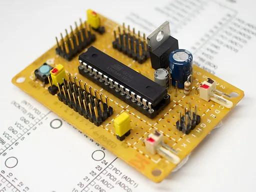
I designed a custom MCU board for my first robot using an ATmega AVR microcontroller, a low-dropout voltage regulator, and flexible power options. It supported ISP programming, multi-MCU compatibility, port expansion, and selectable I/O voltages.
Story
In 2008, as my first step into embedded systems, I designed and assembled the motherboard for my first robot. The core was an ATmega8 AVR microcontroller: an 8-bit RISC device with 8 KB ISP Flash, 1 KB SRAM, 512B EEPROM, and a 6-channel 10-bit ADC, giving me enough headroom for sensor interfacing and actuator control.
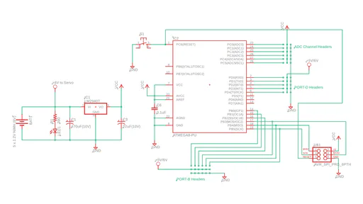
Power management was a real constraint. The board ran from either a 6V adapter or five 1.2V NiMH cells wired in series (up to 7.2V). As those cells discharge, their voltage drops, which would cause the ATmega8 to behave unpredictably. I solved this with the LM2940T low-dropout regulator from National Semiconductor, which sustains a clean 5V output with very little voltage drop and handles up to 1A without needing an external heat sink.
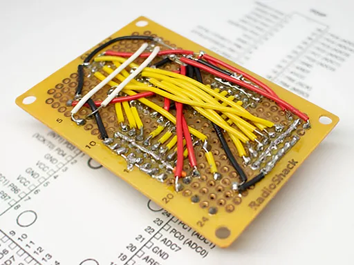
For programming, I used the AVRISP mkII connected via a standard 6-pin ISP header, paired with AVR Studio for compiling and flashing. The board exposed full PORTD (8 pins) and PORTB (6 usable pins) for digital I/O. Two jumpers let me select between 5V and 6V for peripherals, avoiding the need for separate level-shifting circuitry. The layout was pin-compatible with the ATmega48, 88, and 168, so I could upgrade without rewiring. Everything was assembled by hand on perfboard with soldered traces, balancing cost, flexibility, and performance.
Every design decision here reflected one principle I kept coming back to: build for the next version, not just the current one.
He created seven heavens in layers. You will never see any flaw in the creation of the Most Compassionate. Look again: do you see any flaw?
Impacts
- Delivered stable 5V regulation across the full NiMH discharge curve, keeping the robot running reliably on battery
- Pin-compatible with ATmega8, 48, 88, and 168, allowing MCU upgrades without any board redesign
Challenges & Solutions
Challenges
- NiMH battery voltage drops as it discharges, which would destabilize the MCU and sensors
- Some peripherals needed different logic voltages, which would normally require additional level-shifting hardware
- Committing to a single MCU would limit future upgrades without a board redesign
Solutions
- Used the LM2940T low-dropout regulator, which maintains clean 5V output down to a 6V input with minimal heat, requiring no external heat sink
- Added two jumper headers for selecting between 5V MCU logic and 6V direct battery output, covering both cases without extra components
- Laid out the board to be pin-compatible with four ATmega variants, so any of them could be swapped in without rewiring