
My first bare-metal autonomous robot
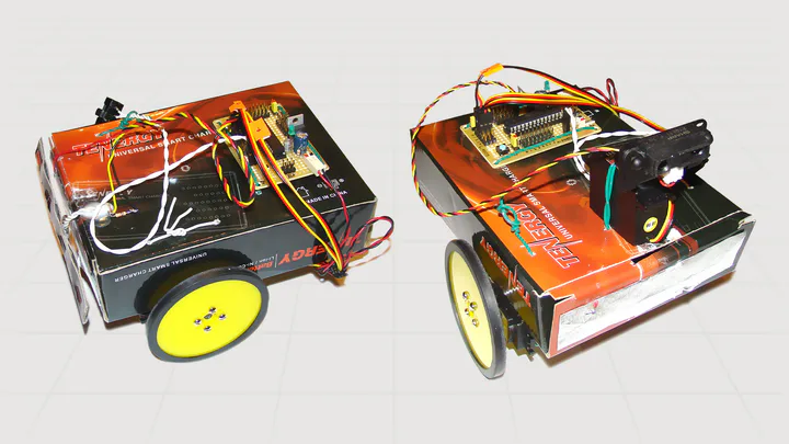
I built my first autonomous robot using an ATmega8, a cardboard chassis, and hand-wired sensors. It evolved from a foil touch sensor to an infrared rangefinder with servo actuators and a MATLAB-calibrated distance model, all written in pure C with no Arduino.
Story
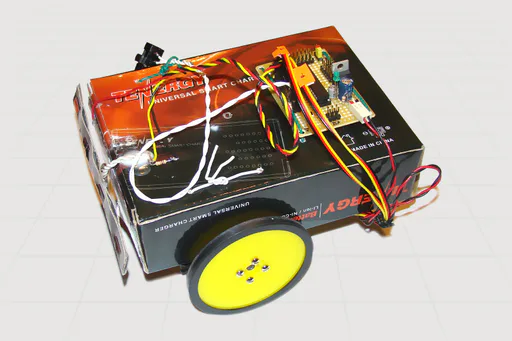
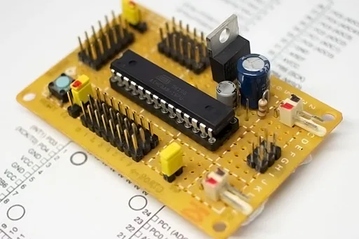
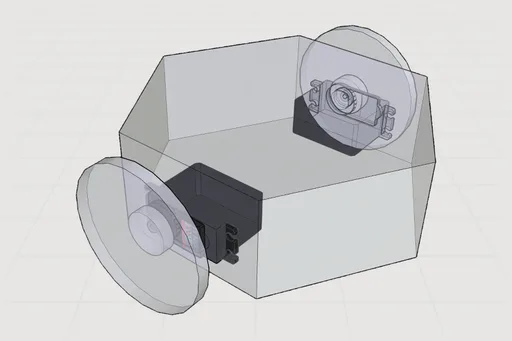
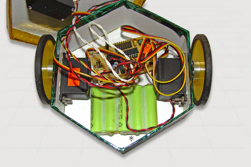
In September 2008, within 24 hours of finishing the ATmega8 motherboard, I assembled my first differential drive robot to validate the control board in motion. With no mechanical parts and no fabrication tools, I cut a chassis from a NiMH charger box and made a touch sensor from aluminum foil. Two Hitec HS311 continuous-rotation servos drove independent wheels for skid-steer navigation.
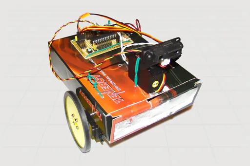
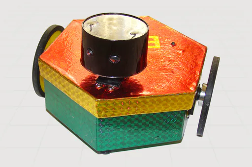
Version 1 used the foil switch as a digital input, triggering an evasive turn on contact. For Version 2, I swapped it with a Sharp GP2Y0A21 infrared rangefinder mounted on a third servo. The robot now scanned left and right, read distances through the ADC, and picked the clearer path. That was behavioral autonomy from raw sensor data, running in 8 KB of Flash and 1 KB of RAM.
All of it was written in pure C inside AVR Studio, compiled to hex, and flashed via the AVRISP mkII. There was no Arduino framework. I configured every register by hand: PORTB for motor PWM, timer outputs for servo timing, and the ADC for IR voltage sampling. Working at that level made the relationship between code and hardware immediate.
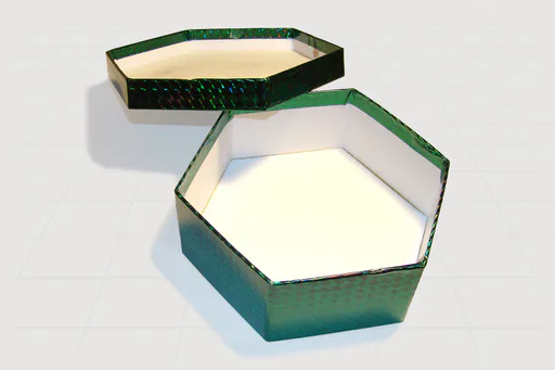
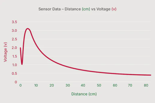
For Version 3, I refined both the aesthetics and the sensing. A hexagonal gift box replaced the rough cardboard. I characterized the IR sensor in MATLAB by logging voltage against known distances, fitted a calibration model to the curve, and embedded that formula in firmware. The robot now worked in real centimeters, not arbitrary ADC counts.
Power came from five 1.2V NiMH cells through the LM2940T LDO, holding a steady 5V throughout. The motherboard’s 6-channel ADC and jumper-selectable I/O tied everything together cleanly.
He is the One Who has perfected everything He created.
Impacts
- Achieved full obstacle avoidance autonomy within 48 hours of completing the motherboard, with no frameworks and no libraries
- Deployed a MATLAB-fitted voltage-to-distance model directly in embedded firmware for real-time sensor calibration
Challenges & Solutions
Challenges
- No mechanical parts, fabrication tools, or 3D printer available for the chassis
- The Sharp GP2Y0A21 IR sensor outputs a nonlinear voltage curve, making raw ADC values unreliable for distance decisions
- Driving continuous-rotation wheel servos and a scanning sensor servo together required precise pulse timing across multiple channels
Solutions
- Cut the chassis from a cardboard box and crafted a touch sensor from aluminum foil for v1, then used a hexagonal gift box for the cleaner v3 build
- Logged voltage vs. distance readings in MATLAB, fitted a calibration curve to the data, and embedded that formula in firmware for real-time distance computation
- Configured AVR timer registers manually and implemented software PWM on PORTB to keep all servo pulses stable directly from the MCU